Sunday, 4 November 2012

Testing the L298N!


I decided to give the L298 a go to see how it works, and was quite happy! It was pretty straightforward, since I already had experience with the TB6612FNG. However, there are some differences. The TB6612FNG has a 'standby' pin which acts as an enable pin for both motors, which I find pretty neat, because it can act as a kill switch, incase something goes wrong. However, this does use up an extra i/o pin, which isn't really a problem (since you can just hook it up to +5V), but is worth mentioning. Another thing that surprised me about the L298 is that it has something called 'current sense' pins. I think they're for measuring current draw from the motors, but I'm not too sure. As a result, in my PCB schematic I left them unconnected. When I tested it out though, it turns out these need to be grounded for the damn thing to work! Not much of a problem, but can still be a pain. At least I didn't send off the design! I made a tutorial on interfacing the thing with Arduino as well, so check it out here!


-nanohex

More PCB fun!

After three increasingly efficient (and difficult to make) designs, I came up with Rev 4! This is the one I'm going to send to the board house for sure, I told myself, and I did! Here's what it looks like (with the copper ground fill):


Notice the groovy rounded corners? I searched around for some PCB design tips and somebody said that most board manufacturers can easily route out custom shapes (as long as they're reasonable!), so I figured why not some rounded corners so I don't cut myself...

Where did I get this manufactured? How much for? What colour solder mask did I use? All valid questions, my friend! I got 10 boards made for a total cost of $35ish, with shipping, at Seeedstudio's "Fusion PCB" service. Their prices were unbeatable, so I went with them. I ordered it in standard green, because other colours cost an extra 10 bucks, which is an unjustifiable cost for a first version! When I sort out any (and hopefully there will be none) bugs, I'll probably get it in something cool like black, with a gold ENIG finish for the plates! Seeedstudio claimed a 4-6 day turnaround to get the boards manufactured, which I was skeptical of, due to some angry comments about boards being 'in production' for months on end, but no problems! I sent them the gerbers on a Friday (after working hours) so production started on the Monday, and on the following Friday (5 days of production time), the order status changed from "in production" to "shipped"! I was actually worried, because I had specified (and paid for) a 10x10 cm maximum size board, and the board was EXACTLY 10 cm one way, if not a teensy bit more when measured from a 1:1 printout. However Eagle's free version has a maximum size of 10x8 cm, so I don't think I went over the limit. In any case, it seems as if they made it without any problems, because it's on its way to me right now!  A nice touch is that Seeedstudio tests 50% of the boards for free (it's an extra $10 to get all boards tested), so at least 5 of my 10 boards should be exactly according to the gerbers! Also, I paid an extra $5 to make it RoHS compliant, since I use lead free solder, and the hot air solder leveling (HASL) process they use to plate the pads should ideally use the same alloy as I use (not sure how much of a difference this makes).

See the cool logo at the bottom? Sadly, I designed it AFTER sending my gerbers, so maybe I'll make it in Rev 2! Thinking of exposing the hexagons, one connected to VCC and one to GND, so I can use it to check voltages/for shorts!

-nanohex

Friday, 26 October 2012

Designing the PCB

Because I've never designed a PCB before, I first needed software (free, of course) to do this! After a little research, I figured Eagle CAD was the best to do this as there are extensive libraries available. The one that would be the most useful for me was, and currently is the SparkFun library, as they have the schematic and footprint of many of the parts I needed to use. They even have a special 'locking' footprint that is designed to hold pins in place upside down with friction so you can solder with ease! However, I didn't dare try anything fancy, since this is my first board. Eagle CAD, and the SparkFun library can be downloaded here:


However, the free version of Eagle does have some restrictions. You can't have a schematic that spans multiple pages, and the maximum board size is 100mm x 80mm. Also, you can't have more than 2 layers of copper (no internal layers). Bummer, but a great program nonetheless.

After watching a few videos on YouTube to learn how to design a PCB and schematic in Eagle, I got started! After much work, and FOUR revisions, I got something I was happy with!


Then, I got cracking on placing the components and routing the board (I avoided the autorouter as much as possible, until the very end, where I got bored...). This was by far the hardest and most tedious part of the process! Some of my early designs looked like this (they don't follow the above schematic, that was my final one):
First attempt. Tried to make it as small as possible, but sticking the LCD out like that is just asking for trouble! Hadn't thought of adding the FT232RL yet.

Rev 2. Much better. In fact, I probably would have sent this board to be made, had I not considered surface mount technology (SMT).


 Much better! I used the SparkFun library for more of the things here, and added space for a heat sink (for the L298N). Still a few bugs though, especially in the silkscreen. When I moved the USB receptacle out so it sticks out of the board (so the plug will actually fit), I forgot to move the silkscreen outline with it! Also, the text at the bottom would have been covered by the LCD once the board is populated (duh!). I changed most of my extra components (resistors, LEDs, capacitors, etc) to surface mount, mostly of an 0805 (2012 metric) size package. This makes the board look much neater and more professional.


A through-hole board. Yuck!
Actually, it's pretty impressive, but nothing compared to a surface mount board.


A much neater looking board!


I was quite happy with the final design, once the bugs were worked out. "This could be the one", I said to myself!

Anyway, for the newbies trying out Eagle for the first time (I'm probably still in that phase), here are some excellent tutorials:

Jeremy Blum has a couple of nice videos explaining how to use Eagle Cad:

Part 1 (Schematic Design)


Part 2 (Board Layout)

Also, SparkFun has a nice page on a similar thing, using an FT232RL breakout as an example (Yay!! I needed to know how to wire up the thing and they have a whole tutorial doing it step by step!!!!)


Finally, there's also a 12-part series (no, I'm not going to embed all the videos here) on youtube. Just search up (on YT) "eagle cad lesson", and you should find a series by a user called rpcelectronics.

-nanohex


The (tiny) first steps to a deadly weapon...

It all begins with an evil laugh:

MWAHAHAHAHA!

...and so I embarked on a quest to design a mini sumo robot to annihilate its opponents (victims)! This evil genius doesn't work alone, though. I'm responsible for the circuitry and the intelligence of the thing, and my partner's supposed to get the mechanical stuff done. I decided, gone are the days of point to point wiring on a $2.00 prototyping board (although these can turn out quite well, if done right), like in some of my early circuits.

This was a simple board that controlled a small obstacle avoiding robot with two modified servos. The MCU has been ripped out (it was either that or wait a couple of days for one to come in the mail, and I'm not the patient type!). I tried to make a more advanced platform with a set of (expensive) SparkFun mecanum wheels, which failed miserably. However, the circuit worked great!
Despite the ugly soldering and a design that sort of built itself as I went along, the thing worked! In both the boards, I couldn't be bothered to add a simple 7HC595 shift register to drive the LED displays, so I just hooked them up to standard output pins.

The rat's nest below. Imagine trying to stick a soldering iron in there.... I still shudder at the memories of cold joints and singed plastic.

I decided for this project, I'm going pro. Yep, that means a proper PCB. And to make it even more awesome, I added some surface mount components in there too, chiefly an FTDI FT232RL chip to add some USB functionality to the thing, because that's just cool. I planned to make it Arduino based (yes, that means AVR), and I thought instead of just buying an Arduino and a bunch of 'shields' (what's up with their stupid names, anyway?) I'm going to make a nice all-in-one board! I still wanted to use the Arduino programming environment for this project, as it's just seamless to work with, but I enjoy programming in straight-up C (with AVR-GCC), so I decided to make something not too Arduino-specific (so I'm not going to confine the board to the idea of having 'set' PWM pins, and having D0 to D13). Of course, any self-respecting board, Arduino or otherwise has some sort of serial communication, hence the FTDI chip. Since this was my first my first SMD experience, I took a crack at some surface mount soldering, which required a soldering iron upgrade.

This was my old soldering iron, and was surprisingly good, despite the nasty mean things people say about gun type irons like this. However, with SMD work, and lead-free solder (lead scares me), I needed one of those fancy temperature-adjustable machines, so I got one fairly cheap off element14, (around $120, with a giant 500g spool of lead-free solder and a brass sponge to clean the tip). 


I could feel the difference right away, soldering with my shiny new iron! It was just so much easier, especially since all the heat didn't wick away the second it touched a pad. The results of my first SMD work were actually pretty good, even though I started with a tiny SSOP-28 package.


I did heat the thing too much though, as I tried to remove a couple of jumpers without solder wick (forgot to buy it!), but everything went better than expected.

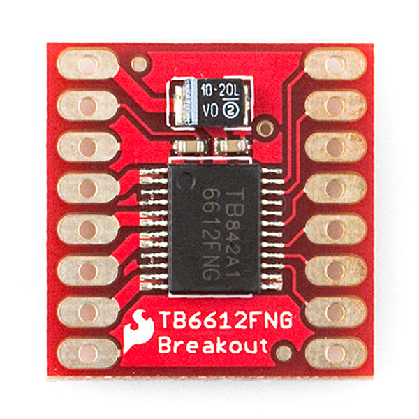
Another thing I had to use was some sort of motor driver. Since the robot's probably going to have tank treads (or some other form of differential drive), two motors should be just right. However, I wanted to stray away from the motor driver I'm used to:


The Toshiba TB6612FNG! It's an amazing little thing, and it's dead simple to use: pull the standby (enable) high, pull either IN1 or IN2 high to set the direction, and sprinkle a little PWM! However, it can only supply a measly 1A per motor, and no deadly robot can run on these tiny motors:


So, I decided it's time for a little hardware upgrade...


...the L298N! This guy can give not 1, but 2 amps of current per motor! Okay, it's still not mind-blowing, but it's something, right? And the some of the boards I've seen with this look sexy! I tried to figure out why they looked so cool, and I figured out it's the big heat sink that really stands out.


The final 'big' part I absolutely had to include was a 16x2 alphanumeric LCD display (standard HD44780 controller). These things just look amazing when hooked up right, and can be quite useful for debugging purposes, especially for a robotics competition, where hooking up the board to a computer for serial debugging can be impractical. So, for just around $2.50, including shipping, I picked up one of these from eBay:


It works perfectly, and comes in a cool blue colour! I saw literally the exact same thing in a local store selling for $20.00, and I almost bought it. Good thing I didn't! Came to my doorstep in just under 2 weeks (from Hong Kong). I also picked up a couple of smaller 8x2 screens, but those are a little too tiny for my taste.

Now for the next challenge... drawing up a schematic and designing a board!

-nanohex